OSPF (Open Shortest Path First) protocol was developed due to a need in the internet community to introduce a high functionality non-proprietary Internal Gateway Protocol (IGP) for the TCP/IP protocol family. The discussion of creating a common interoperable IGP for the Internet started in 1988 and did not get formalized until 1991. At that time the OSPF Working Group requested that OSPF be considered for advancement to Draft Internet Standard.
The OSPF protocol is based on link-state technology which is a departure from the Bellman-Ford vector based algorithms used in traditional Internet routing protocols such as RIP. OSPF has introduced new concepts such as authentication of routing updates, Variable Length Subnet Masks (VLSM), route summarization, etc.
In the following chapters we will discuss the OSPF terminology, algorithm and the pros and cons of the protocol in designing the large and complicated networks of today.
The rapid growth and expansion of today's networks has pushed RIP to its limits. RIP has certain limitations that could cause problems in large networks:
Some enhancements were introduced in a new version of RIP called RIP2. RIP2 addresses the issues of VLSM, authentication, and multicast routing updates. RIP2 is not a big improvement over RIP (now called RIP 1) because it still has the limitations of hop counts and slow convergence which are essential in todays large networks.
OSPF, on the other hand, addresses most of the issues presented above:
This of course would lead to more complexity in configuring and troubleshooting OSPF networks. Administrators that are used to the simplicity of RIP will be challenged with the amount of new information they have to learn in order to keep up with OSPF networks. Also, this will introduce more overhead in memory allocation and CPU utilization. Some of the routers running RIP might have to be upgraded in order to handle the overhead caused by OSPF.
OSPF is a link-state protocol. We could think of a link as being an interface on the router. The state of the link is a description of that interface and of its relationship to its neighboring routers. A description of the interface would include, for example, the IP address of the interface, the mask, the type of network it is connected to, the routers connected to that network and so on. The collection of all these link-states would form a link-state database.
OSPF uses a link-state algorithm in order to build and calculate the shortest path to all known destinations. The algorithm by itself is quite complicated. The following is a very high level, simplified way of looking at the various steps of the algorithm:
1- Upon initialization or due to any change in routing information, a router will generate a link-state advertisement. This advertisement will represent the collection of all link-states on that router.
2- All routers will exchange link-states by means of flooding. Each router that receives a link-state update should store a copy in its link-state database and then propagate the update to other routers.
3- After the database of each router is completed, the router will calculate a Shortest Path Tree to all destinations. The router uses the Dijkstra algorithm to calculate the shortest path tree. The destinations, the associated cost and the next hop to reach those destinations will form the IP routing table.
4- In case no changes in the OSPF network occur, such as cost of a link or a network being added or deleted, OSPF should be very quiet. Any changes that occur are communicated via link-state packets, and the Dijkstra algorithm is recalculated to find the shortest path.
The shortest path is calculated using the Diskjtra algorithm. The algorithm places each router at the root of a tree and calculates the shortest path to each destination based on the cumulative cost required to reach that destination. Each router will have its own view of the topology even though all the routers will build a shortest path tree using the same link-state database. The following sections indicate what is involved in building a shortest path tree.
The cost (also called metric) of an interface in OSPF is an indication of the overhead required to send packets across a certain interface. The cost of an interface is inversely proportional to the bandwidth of that interface. A higher bandwidth indicates a lower cost. There is more overhead (higher cost) and time delays involved in crossing a 56k serial line than crossing a 10M ethernet line. The formula used to calculate the cost is:
cost= 10000 0000/bandwith in bps
For example, it will cost 10 EXP8/10 EXP7 = 10 to cross a 10M ethernet line and will cost 10 EXP8/1544000 = 64 to cross a T1 line.
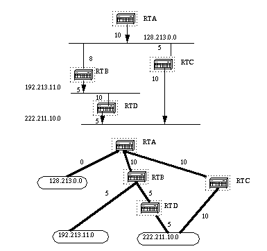
Assume we have the following network diagram with the indicated interface costs. In order to build the shortest path tree for RTA, we would have to make RTA the root of the tree and calculate the smallest cost for each destination.

The above is the view of the network as seen from RTA. Note the direction of the arrows in calculating the cost. For example, the cost of RTB's interface to network 128.213.0.0 is not relevant when calculating the cost to 192.213.11.0. RTA can reach 192.213.11.0 via RTB with a cost of 15 (10+5). RTA can also reach 222.211.10.0 via RTC with a cost of 20 (10+10) or via RTB with a cost of 20 (10+5+5).
After the router builds the shortest path tree, it will start building the routing table accordingly. Directly connected networks will be reached via a metric (cost) of 0 and other networks will be reached according to the cost calculated in the tree.
As previously mentioned, OSPF uses flooding to exchange link-state updates between routers. Any change in routing information is flooded to all routers in the network. Areas are introduced to put a boundary on the explosion of link-state updates. Flooding and calculation of the Dijkstra algorithm on a router is limited to changes within an area. All routers within an area have the exact link-state database. Routers that belong to multiple areas, called area border routers (ABR), have the duty of disseminating routing information or routing changes between areas.
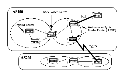
An area is interface specific. A router that has all of its interfaces within the same area is called an internal router (IR). A router that has interfaces in multiple areas is called an area border router (ABR). Routers that act as gateways (redistribution)between OSPF and other routing protocols (IGRP, EIGRP, IS-IS, RIP, BGP, Static) or other instances of the OSPF routing process are called autonomous system border routers (ASBR). Any router can be an ABR or an ASBR.
There are different types of Link State Packets, those are what you normally see in an OSPF database (Appendix A). The different types are illustrated in the following diagram:
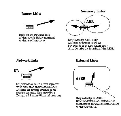
As indicated above, the router links are an indication of the state of the interfaces on a router belonging to a certain area. Each router will generate a router link for all of its interfaces. Summary links are generated by ABRs; this is how network reachability information is disseminated between areas. Normally, all information is injected into the backbone (area 0) and in turn the backbone will pass it on to other areas. ABRs also have the task of propagating the reachability of the ASBR. This is how routers know how to get to external routes in other ASs.
Network Links are generated by a Designated Router (DR) on a segment (DRs will be discussed later). This information is an indication of all routers connected to a particular multi-access segment such as Ethernet, Token Ring and FDDI (NBMA also).
External Links are an indication of networks outside of the AS. These networks are injected into OSPF via redistribution. The ASBR has the task of injecting these routes into an autonomous system.
It is possible to authenticate the OSPF packets such that routers can participate in routing domains based on predefined passwords. By default, a router uses a Null authentication which means that routing exchanges over a network are not authenticated. Two other authentication methods exist: Simple password authentication and Message Digest authentication (md5).
Message Digest Authentication is a cryptographic authentication. A key (password) and key-id are configured on each router. The router uses an algorithm based on the OSPF packet, the key, and the key-id to generate a "message digest" that gets appended to the packet. Unlike the simple authentication, the key is not exchanged over the wire. A non-decreasing sequence number is also included in each OSPF packet to protect against replay attacks.
This method also allows for uninterrupted transitions between keys. This is helpful for administrators who wish to change the OSPF password without disrupting communication. If an interface is configured with a new key, the router will send multiple copies of the same packet, each authenticated by different keys. The router will stop sending duplicate packets once it detects that all of its neighbors have adopted the new key.
OSPF has special restrictions when multiple areas are involved. If more than one area is configured, one of these areas has be to be area 0. This is called the backbone. When designing networks it is good practice to start with area 0 and then expand into other areas later on.
The backbone has to be at the center of all other areas, i.e. all areas have to be physically connected to the backbone. The reasoning behind this is that OSPF expects all areas to inject routing information into the backbone and in turn the backbone will disseminate that information into other areas. The following diagram will illustrate the flow of information in an OSPF network:
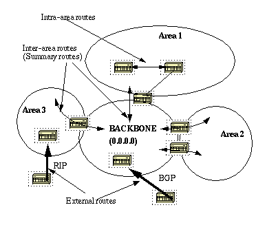
In the above diagram, all areas are directly connected to the backbone. In the rare situations where a new area is introduced that cannot have a direct physical access to the backbone, a virtual link will have to be configured. Virtual links will be discussed in the next section. Note the different types of routing information. Routes that are generated from within an area (the destination belongs to the area) are called intra-area routes. These routes are normally represented by the letter O in the IP routing table. Routes that originate from other areas are called inter-area or Summary routes. The notation for these routes is O IA in the IP routing table. Routes that originate from other routing protocols (or different OSPF processes) and that are injected into OSPF via redistribution are called external routes. These routes are represented by O E2 or O E1 in the IP routing table. Multiple routes to the same destination are preferred in the following order: intra-area, inter-area, external E1, external E2. External types E1 and E2 will be explained later.
Virtual links are used for two purposes:
1- Linking an area that does not have a physical connection to the backbone.
2- Patching the backbone in case discontinuity of area 0 occurs.
As mentioned earlier, area 0 has to be at the center of all other areas. In some rare case where it is impossible to have an area physically connected to the backbone, a virtual link is used. The virtual link will provide the disconnected area a logical path to the backbone. The virtual link has to be established between two ABRs that have a common area, with one ABR connected to the backbone. This is illustrated in the following example:
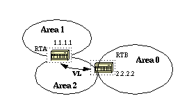
In this example, area 1 does not have a direct physical connection into area 0. A virtual link has to be configured between RTA and RTB. Area 2 is to be used as a transit area and RTB is the entry point into area 0. This way RTA and area 1 will have a logical connection to the backbone.
OSPF allows for linking discontinuous parts of the backbone using a virtual link. In some cases, different area 0s need to be linked together. This can occur if, for example, a company is trying to merge two separate OSPF networks into one network with a common area 0. In other instances, virtual-links are added for redundancy in case some router failure causes the backbone to be split into two. Whatever the reason may be, a virtual link can be configured between separate ABRs that touch area 0 from each side and having a common area. This is illustrated in the following example:
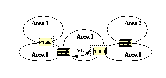
In the above diagram two area 0s are linked together via a virtual link. In case a common area does not exist, an additional area, such as area 3, could be created to become the transit area.
In case any area which is different than the backbone becomes partitioned, the backbone will take care of the partitioning without using any virtual links. One part of the partioned area will be known to the other part via inter-area routes rather than intra-area routes.
Routers that share a common segment become neighbors on that segment. Neighbors are elected via the Hello protocol. Hello packets are sent periodically out of each interface using IP multicast (Appendix B). Routers become neighbors as soon as they see themselves listed in the neighbor's Hello packet. This way, a two way communication is guaranteed. Neighbor negotiation applies to the primary address only. Secondary addresses can be configured on an interface with a restriction that they have to belong to the same area as the primary address.
Two routers will not become neighbors unless they agree on the following:
1- Area-id: Two routers having a common segment; their interfaces have to belong to the same area on that segment. Of course, the interfaces should belong to the same subnet and have a similar mask.
2- Authentication: OSPF allows for the configuration of a password for a specific area. Routers that want to become neighbors have to exchange the same password on a particular segment.
3- Hello and Dead Intervals: OSPF exchanges Hello packets on each segment. This is a form of keepalive used by routers in order to acknowledge their existence on a segment and in order to elect a designated router (DR) on multiaccess segments.The Hello interval specifies the length of time, in seconds, between the hello packets that a router sends on an OSPF interface. The dead interval is the number of seconds that a router's Hello packets have not been seen before its neighbors declare the OSPF router down.
OSPF requires these intervals to be exactly the same between two neighbors. If any of these intervals are different, these routers will not become neighbors on a particular segment.
4- Stub area flag: Two routers have to also agree on the stub area flag in the Hello packets in order to become neighbors. Stub areas will be discussed in a later section. Keep in mind for now that defining stub areas will affect the neighbor election process.
An adjacency is the next step after the neighboring process. Adjacent routers are routers who go beyond the simple Hello exchange and proceed into the database exchange process. In order to minimize the amount of information exchange on a particular segment, OSPF elects one router to be a designated router (DR), and one router to be a backup designated router (BDR) on each multi-access segment. The BDR is elected as a backup mechanism in case the DR goes down. The idea behind this is that routers have a central point of contact for information exchange. Instead of each router exchanging updates with every other router on the segment, every router will exchange the information with the DR and BDR. The DR and BDR will relay the information to everybody else. In mathematical terms this would cut the information exchange from O(n*n) to O(n) where n is the number of routers on a multi-access segment. The following router model will illustrate the DR and BDR:
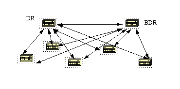
In the above diagram, all routers share a common multi-access segment. Due to the exchange of Hello packets, one router is elected DR and another is elected BDR. Each router on the segment (which already became a neighbor) will try to establish an adjacency with the DR and BDR.
DR and BDR election is done via the Hello protocol. Hello packets are exchanged via IP multicast packets (Appendix B) on each segment. The router with the highest OSPF priority on a segment will become the DR for that segment. The same process is repeated for the BDR. In case of a tie, the router with the highest RID will win. The default for the interface OSPF priority is one. Remember that the DR and BDR concepts are per multiaccess segment.
A priority value of zero indicates an interface which is not to be elected as DR or BDR. The state of the interface with priority zero will be DROTHER. The following diagram illustrates the DR election:
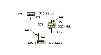
In the above diagram, RTA and RTB have the same interface priority but RTB has a higher RID. RTB would be DR on that segment. RTC has a higher priority than RTB. RTC is DR on that segment.
The adjacency building process takes effect after multiple stages have been fulfilled. Routers that become adjacent will have the exact link-state database. The following is a brief summary of the states an interface passes through before becoming adjacent to another router:
1- Down: No information has been received from anybody on the segment.
1'- Attempt: On non-broadcast multi-access clouds such as Frame Relay and X.25, this state indicates that no recent information has been received from the neighbor. An effort should be made to contact the neighbor by sending Hello packets at the reduced rate PollInterval.
2- Init: The interface has detected a Hello packet coming from a neighbor but bi-directional communication has not yet been established.
3- Two-way: There is bi-directional communication with a neighbor. The router has seen itself in the Hello packets coming from a neighbor. At the end of this stage the DR and BDR election would have been done. At the end of the 2way stage, routers will decide whether to proceed in building an adjacency or not. The decision is based on whether one of the routers is a DR or BDR or the link is a point-to-point or a virtual link.
4- Exstart: Routers are trying to establish the initial sequence number that is going to be used in the information exchange packets. The sequence number insures that routers always get the most recent information. One router will become the primary and the other will become secondary. The primary router will poll the secondary for information.
5- Exchange: Routers will describe their entire link-state database by sending database description packets. At this state, packets could be flooded to other interfaces on the router.
6- Loading: At this state, routers are finalizing the information exchange. Routers have built a link-state request list and a link-state retransmission list. Any information that looks incomplete or outdated will be put on the request list. Any update that is sent will be put on the retransmission list until it gets acknowledged.
7- Full: At this state, the adjacency is complete. The neighboring routers are fully adjacent. Adjacent routers will have a similar link-state database.
Example:
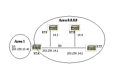
RTA, RTB, RTD, and RTF share a common segment (E0) in area 0.0.0.0.
Let us look at RTA. Ethernet0 is in area 0.0.0.0. The process ID is 10 (router ospf 10) and the router ID is 203.250.13.41. Remember that the RID is the highest IP address on the box or the loopback interface, calculated at boot time or whenever the OSPF process is restarted. The state of the interface is BDR. Since all routers have the same OSPF priority on Ethernet 0 (default is 1), RTF's interface was elected as DR because of the higher RID. In the same way, RTA was elected as BDR. RTD and RTB are neither a DR or BDR and their state is DROTHER.
Also note the neighbor count and the adjacent count. RTD has three neighbors and is adjacent to two of them, the DR and the BDR. RTF has three neighbors and is adjacent to all of them because it is the DR.
The information about the network type is important and will determine the state of the interface. On broadcast networks such as Ethernet, the election of the DR and BDR should be irrelevant to the end user. It should not matter who the DR or BDR are. In other cases, such as NBMA media such as Frame Relay and X.25, this becomes very important for OSPF to function correctly. Fortunately, with the introduction of point-to-point and point-to-multipoint subinterfaces, DR election is no longer an issue. OSPF over NBMA will be discussed in the next section.
OSPF will always form an adjacency with the neighbor on the other side of a point-to-point interface such as point-to-point serial lines. There is no concept of DR or BDR. The state of the serial interfaces is point to point.
Special care should be taken when configuring OSPF over multi-access non-broadcast medias such as Frame Relay, X.25, ATM. The protocol considers these media like any other broadcast media such as Ethernet. NBMA clouds are usually built in a hub and spoke topology. PVCs or SVCs are laid out in a partial mesh and the physical topology does not provide the multi access that OSPF believes is out there. The selection of the DR becomes an issue because the DR and BDR need to have full physical connectivity with all routers that exist on the cloud. Also, because of the lack of broadcast capabilities, the DR and BDR need to have a static list of all other routers attached to the cloud.
A neighbor with priority 0 is considered ineligible for DR election. The "poll-interval" is the amount of time an NBMA interface waits before polling (sending a Hello) to a presumably dead neighbor. The neighbor command applies to routers with a potential of being DRs or BDRs (interface priority not equal to 0). The following diagram shows a network diagram where DR selection is very important:
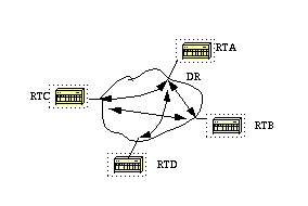
In the above diagram, it is essential for RTA's interface to the cloud to be elected DR. This is because RTA is the only router that has full connectivity to other routers. The election of the DR could be influenced by setting the ospf priority on the interfaces. Routers that do not need to become DRs or BDRs will have a priority of 0 other routers could have a lower priority.
Section 1 Section 2 Section 3 Section 4 Section 5